

-
Here's some links on how to set up Torque to work with the S oul EV. (It also works on the Hyundai Ioniq Electric).
It would be really great if someone could create one of these help pages specifically for the Ioniq.
And report back on how these codes are working. Preferably on one of the other sites because I visit this site infrequently.
The original web page and discussion for these codes is on this forum - Setting up Torque to show BMS data
The main repository for the codes has since moved to github - https://github.com/JejuSoul/OBD-PIDs-for-HKMC-EVs
There is help in English here - Setting up Torque Pro to show OBD data on Hyundai / Kia Electric Vehicles
There is help in French here - Kia SOUL EV : comment lire les différents capteurs via OBD-II
There is help in French here - [Diagnostique OBD2] Torque Pro -Android- et le Kia Soul EV.
There is help in Korean here - 토크프로 중급편 (TORQUE) 확장PID 관리 하기
-----------------------------------
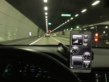
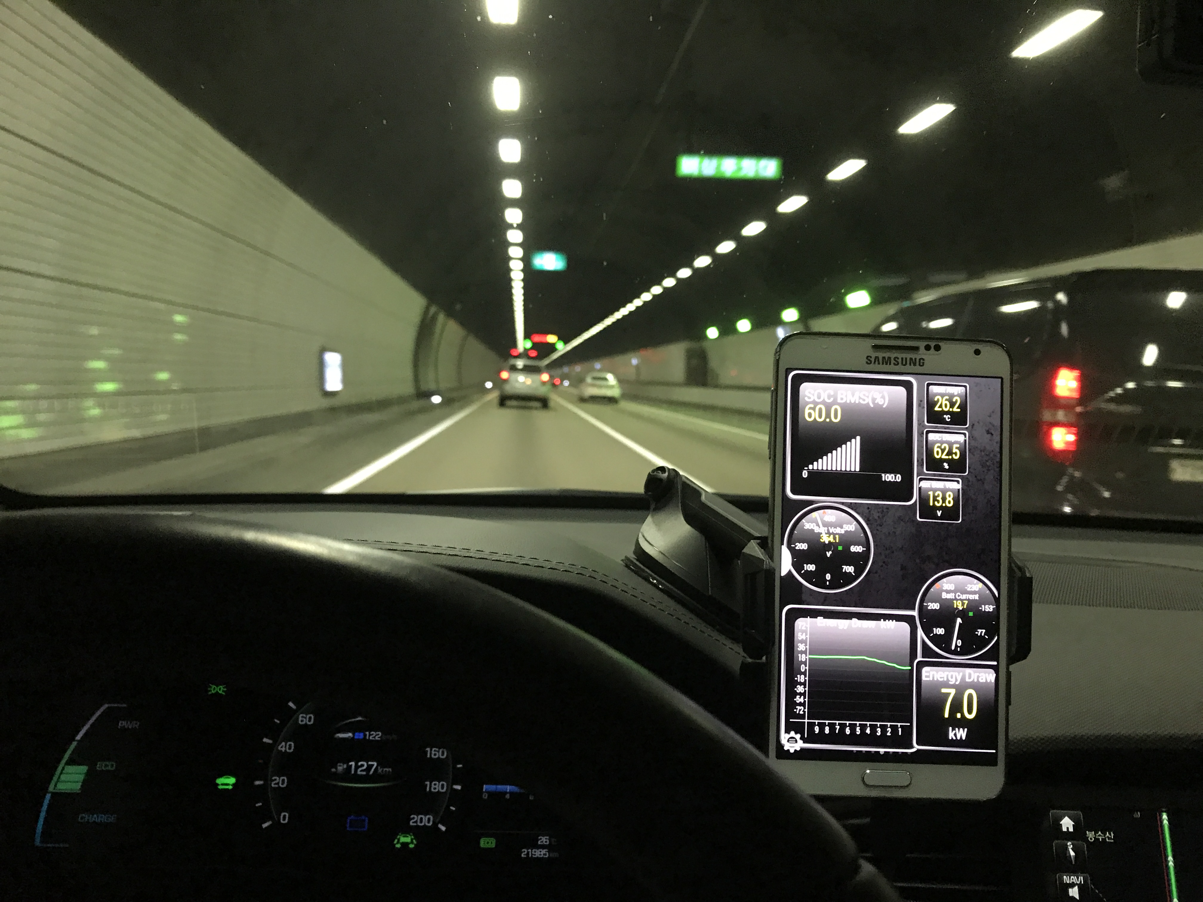
Here's Torque running on an Ioniq Electric in Korea.
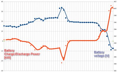
Nice graphic from German Ioniq user. Car starts at 100% SOC on top of small hill. Recuperates on the way down. and increases the batteries voltage.
Here's some links on how to set up Torque to work with the S oul EV. (It also works on the Hyundai Ioniq Electric).
It would be really great if someone could create one of these help pages specifically for the Ioniq.
And report back on how these codes are working. Preferably on one of the other sites because I visit this site infrequently.
The original web page and discussion for these codes is on this forum - Setting up Torque to show BMS data
The main repository for the codes has since moved to github - https://github.com/JejuSoul/OBD-PIDs-for-HKMC-EVs
There is help in English here - Setting up Torque Pro to show OBD data on Hyundai / Kia Electric Vehicles
There is help in French here - Kia SOUL EV : comment lire les différents capteurs via OBD-II
There is help in French here - [Diagnostique OBD2] Torque Pro -Android- et le Kia Soul EV.
There is help in Korean here - 토크프로 중급편 (TORQUE) 확장PID 관리 하기
-----------------------------------
Here's Torque running on an Ioniq Electric in Korea.
Nice graphic from German Ioniq user. Car starts at 100% SOC on top of small hill. Recuperates on the way down. and increases the batteries voltage.


